Inspiration
Based upon the good work of tjclement/esp-dimmer-hardware.
While TJCLEMENT's verson 2 board was good, I had trouble getting recovering my ESP when an over-the-air firmware update failed.
Schematic
My schematic has some modifications:
- Added an FTDI programming port.
- Made the resistors on the outputs pull-down rather than in-line to the MOSFET.
- Added an extra IO connector with GND/3.3V to attach a potentiometer for input.
![Schematic [click for full size]](/story-content-files/esp8266_12v_led_driver/schematic.jpg)
PCB
The PCB is bigger, mainly because I have the space in my application but also (slightly) because of the additional ports.
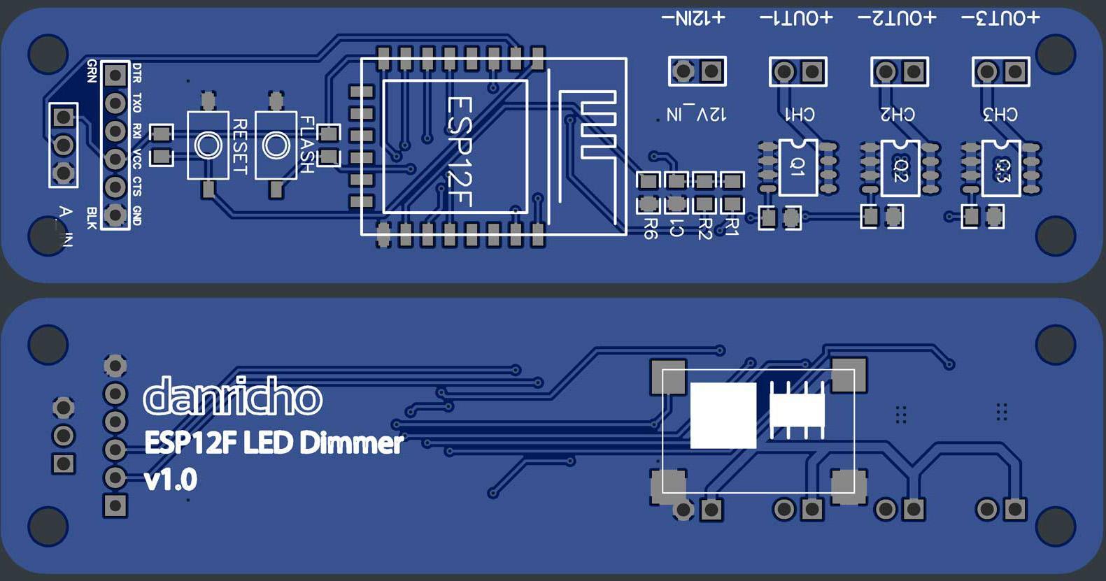
I ordered the PCB from JLCPCB.
BOM
Most parts are sourced from the sister company of JLCPCB, called LCSC.
The power regulation module can be found on AliExpress with the search "MINI-360".
| Name | # | Manufacturer | LCSC PN |
|---|---|---|---|
| ESP-12F | 1 | Ai-Thinker | C82891 |
| 0805 10K Resitors | 8 | UniOhm | C149504 |
| 0808 100nF Cap | 1 | HEC | C105951 |
| FDS8896 | 3 | ON Semicon | C241820 |
| K2-1107ST-A4SW-06 | 2 | SMD Switches | C118141 |
| MP2307-MINI-360 | 1 | AliExpress - search "MINI-360" |
I haven't included the I/O connectors. All are 2.54 pitch and header strips or screw connectors can be used.
Assembly
When assembling, solder the power regulation module first and set it to 3.3V output with the 12V input applied.
This ensures you wont blow up the ESP.
Firmware
The firmware I use makes it play with OpenHab2 overMQTT.
Mine is very specific to my setup, but here is a cut-down version:
// I only use channel 1 as my strip is white not RGB
#define outputPin 13          // first channel (CH 1 / OUT1)
#define analogInPin A0        // potentiometer pin (A_IN on PCB)
#define onboardLED 2          // led on ESP module (for indications)
int outputBrightness = 0;     // current output brightness
int lastOutputBrightness = 0; // previous output brightness
int potSetting = 0;           // current read from the pot
int lastPotSetting = 0;       // previous read from the pot

void setup() {

  analogWriteFreq(40000);   // this stops any flicker by increasing the PWM frequency

  pinMode(outputPin, OUTPUT);
  pinMode(onboardLED, OUTPUT);

  // turn off the output at start
  analogWrite(outputPin, 0);

  // indicate that the code is running on the onboard LED
  digitalWrite(onboardLED, 0 );
  delay(50);
  digitalWrite(onboardLED, 1 );
  delay(50);
  digitalWrite(onboardLED, 0 );
  delay(50);
  digitalWrite(onboardLED, 1 );

  // setup Wifi here
  // setup MQTT connection here...

}

void loop() {

  delay(100);             // slow down the loop
  long now = millis();    // current timestamp

  // reconnect to Wifi and MQTT if they have dropped out here.

  // this reads the potentiometer value and maps it from the ADC ranges (4-590)
  // to potSetting which is a percent (0-100). Range 4-590 was derived by test.
  potSetting = map(analogRead(analogInPin), 4, 590, 0, 100);
  potSetting = (potSetting+10)/20*20; // round to nearest 20%

  // this checks for a legitimate change in potentiometer setting
  if (abs(lastPotSetting - potSetting) > 1 ){
    lastPotSetting = potSetting;
    outputBrightness = potSetting;
  }

  // this checks if we need to update the output brightness
  // Note: MQTT commanded changes are handles elsewhere in the code
  if (abs(lastOutputBrightness - outputBrightness) > 0){
    lastOutputBrightness = outputBrightness;

    // this sets the duty cycle to a value between 0-1023 based on the
    // outputBrightness which is a percent (0-100).
    analogWrite(outputPin, map(outputBrightness,0,100,0,1023) );

    // indicate a new setting on onboard LED
    digitalWrite(onboardLED, 0 );
    delay(50);
    digitalWrite(onboardLED, 1 );

    // also notify MQTT that a change has happened.
  }

}