Intro
originally published on wordpress.com
This is a demonstration of how to use a real time clock with Arduino.
This can be helpful when making clocks as well as keeping logs of events.
Parts
- Arduino Uno (or similar)
- RTC module (eBay / SparkFun: ds1307 RTC module
- some tactile switches for the adjustment push-buttons
Circuit
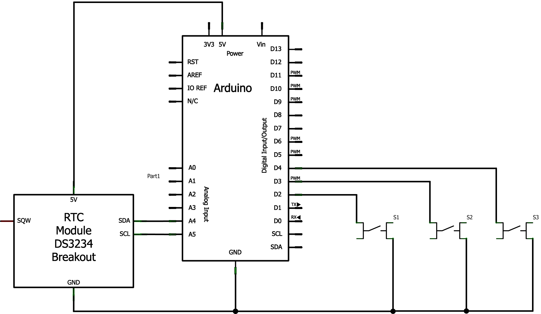
I planned what I did using Fritzing Note: The switches don't have pull up resistors as I utilised the internal pull up resisters of the digital Arduino pins.
Here is the Fritzing schematic:
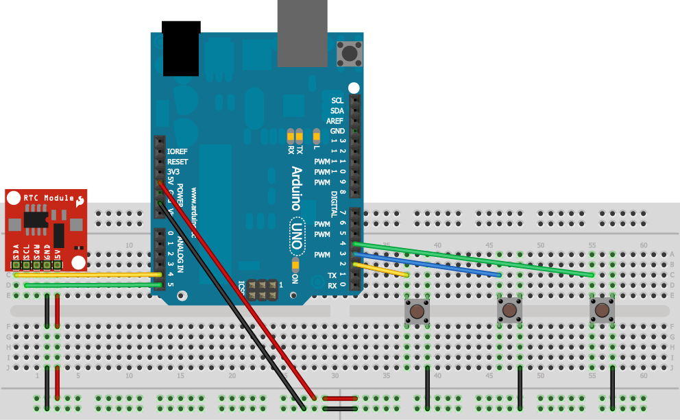
Here is the Fritzing virtual breadboard layout:
Here is the actual circuit on a breadboad:

Once implemented, and the code is on the Arduino, if the Serial Monitor is opened you should see something like this:

This is handy as the buttons allow for the adjustment of time on the RTC by using an on-board time variable as an intermediary step.
The source code below is commented and should help further.
#include <Time.h>
#include <Wire.h>
#include <DS1307RTC.h>  // a basic DS1307 library that returns time as a time_t

void setup()  {
  Serial.begin(9600); // start the serial connectio
  n to the PC.

  pinMode(2, INPUT);       // set pin 2 as an input
  digitalWrite(2, HIGH);   // activate internal pullup resistor on pin 2
  pinMode(3, INPUT);       // set pin 3 as an input
  digitalWrite(3, HIGH);   // activate internal pullup resistor on pin 3
  pinMode(4, INPUT);       // set pin 4 as an input
  digitalWrite(4, HIGH);   // activate internal pullup resistor on pin 4

  setSyncProvider(RTC.get);   // the function to get the time from the RTC
  setSyncInterval(60);        // set the number of seconds between re-sync

  if(timeStatus()!= timeSet)
     Serial.println("Unable to sync with the RTC.");
  else
     Serial.println("RTC has been read.");
}

void loop()
{
  if (digitalRead(2) == LOW) {         // Zero the minutes!
                                       // setting the onboard time to 0 minutes.
    setTime(hour(),0,second(),day(),month(), year());
    RTC.set(now());                    // sending the onboard time to the RTC.
    Serial.println("Minutes Reset.");  // send confirmation to the PC.

  }

  // *** had to adjust the adjustTime function in the Time library.
  // Inside Time.cpp, the adjustTime method was replaced with:
  //
  //  void adjustTime(long adjustment){
  //    setTime(sysTime + adjustment);
  //  }
  //

  if (digitalRead(3) == LOW) {         // add an hour!
    adjustTime(3600);                  // adjust onboard time by +3600 seconds (1hr) ***
    RTC.set(now());                    // sending the onboard time to the RTC.
    Serial.println("Added an hour.");  // send confirmation to the PC.
  }

  if (digitalRead(4) == LOW) {         // add a minute!
    adjustTime(60);                    // adjust onboard time by +60 seconds (1min) ***
    RTC.set(now());                    // sending the onboard time to the RTC.
    Serial.println("Added a minute."); // send confirmation to the PC.
  }

  // this section is for setting the rtc chip from the serial terminal.
  if(Serial.available()){
     time_t t = processSyncMessage();
     if(t >0)
     {
        RTC.set(t);   // set the RTC and the system time to the received value
        setTime(t);
     }
  }

  digitalClockDisplay();  // sends an update of the time to the PC.
  delay(1000);            // wait for a bit.
}

void digitalClockDisplay(){
  // digital clock display of the time over serial
  Serial.print(hour());
  Serial.print(":");
  printDigits(minute());
  Serial.print(":");
  printDigits(second());
  Serial.println();

}

void printDigits(int digits){
  // utility function for digital clock display: prints preceding colon and leading 0
  if(digits < 10)
    Serial.print('0');
  Serial.print(digits);
}

/*  code to process time sync messages from the serial port   */
#define TIME_MSG_LEN  11   // time sync to PC is HEADER followed by unix time_t as ten ascii digits
#define TIME_HEADER  'T'   // Header tag for serial time sync message

time_t processSyncMessage() {
  // return the time if a valid sync message is received on the serial port.
  while(Serial.available() >=  TIME_MSG_LEN ){  // time message consists of a header and ten ascii digits
    char c = Serial.read() ;
    Serial.print(c);
    if( c == TIME_HEADER ) {
      time_t pctime = 0;
      for(int i=0; i < TIME_MSG_LEN -1; i++){
        c = Serial.read();
        if( c >= '0' && c <= '9'){
          pctime = (10 * pctime) + (c - '0') ; // convert digits to a number
        }
      }
      return pctime;
    }
  }
  return 0;
}