Intro
originally published on wordpress.com
When it come to outputs from microcontrollers, you just about can't beat LEDs.
So what better way we use what we learned in the shift register story than to learn about LED Matrix displays!
Refresher
If you didn't read the Arduino tutorial last time, now might be a good time (particularly "example 2") [here].
Also for a quick revision on the shift register concept here is an animation.
So this time we are hooking up two 74HC595 shift registers to the Arduino and using the 16 outputs to drive the rows and columns for an LED Matrix.
Note: There needs to be current limiting resistors on either the column or row pins to protect the LEDs.
How?
First, go ahead and setup one shift register as before, then we add another one beside it.
We use a common clock and latch between the two, but feed the data into the first and feed the overflow of the first into the second.
This means if we "shiftout" the column data first (active has as it is fed into the anode); then "shiftout" the row data (inverted to active low - cathode); we will get control of each individual led.
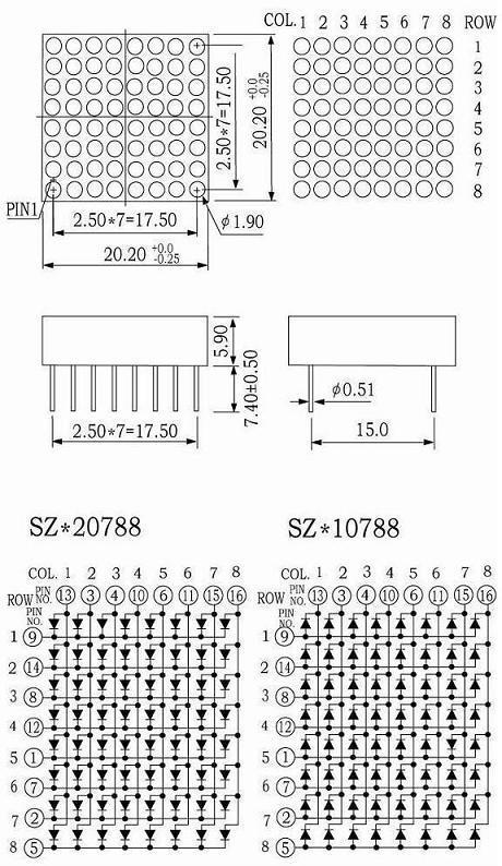
The circuit diagram for the matrix is below:
Demo Video
Quick YouTube video demo.
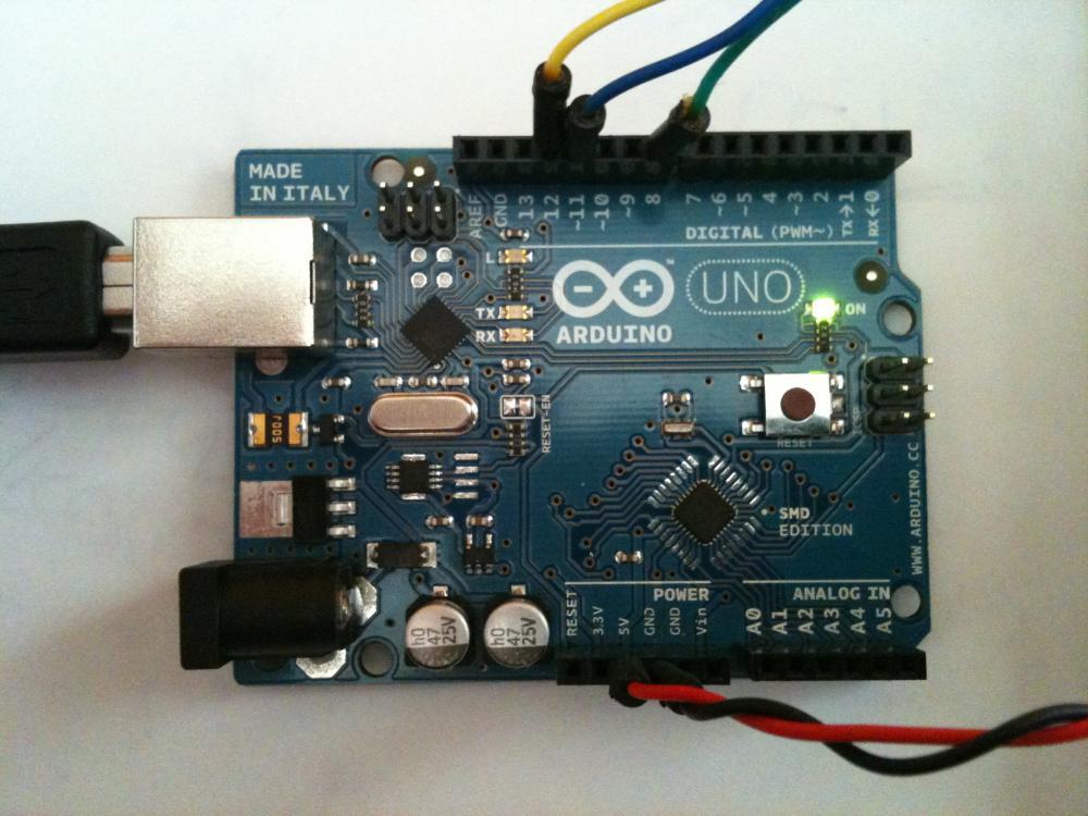
Pictures
Some pictures (might help - its a mess due to the LED Matrix's pin layout.):


The Code
int latchPin = 8;
int clockPin = 12;
int dataPin = 11;

byte column[8] = {128,64,32,16,8,4,2,1};
byte row[8];

void setup() {
  pinMode(latchPin, OUTPUT);
  pinMode(clockPin, OUTPUT);
  pinMode(dataPin, OUTPUT);
}

void loop() {
  for (int character = 0; character < 11; character ++){
    switch (character) {
      case 0:
        row[0] = 0b00000000;
        row[1] = 0b00011000;
        row[2] = 0b00100100;
        row[3] = 0b00101100;
        row[4] = 0b00110100;
        row[5] = 0b00100100;
        row[6] = 0b00011000;
        row[7] = 0b00000000;
        break;
      case 1:
        row[0] = 0b00000000;
        row[1] = 0b00010000;
        row[2] = 0b00110000;
        row[3] = 0b00010000;
        row[4] = 0b00010000;
        row[5] = 0b00010000;
        row[6] = 0b00111000;
        row[7] = 0b00000000;
        break;
      case 2:
        row[0] = 0b00000000;
        row[1] = 0b00011000;
        row[2] = 0b00100100;
        row[3] = 0b00000100;
        row[4] = 0b00011000;
        row[5] = 0b00100000;
        row[6] = 0b00111100;
        row[7] = 0b00000000;
        break;
      case 3:
        row[0] = 0b00000000;
        row[1] = 0b00111000;
        row[2] = 0b00000100;
        row[3] = 0b00011000;
        row[4] = 0b00000100;
        row[5] = 0b00000100;
        row[6] = 0b00111000;
        row[7] = 0b00000000;
        break;
      case 4:
        row[0] = 0b00000000;
        row[1] = 0b00100000;
        row[2] = 0b00101000;
        row[3] = 0b00101000;
        row[4] = 0b00111100;
        row[5] = 0b00001000;
        row[6] = 0b00001000;
        row[7] = 0b00000000;
        break;
      case 5:
        row[0] = 0b00000000;
        row[1] = 0b00111100;
        row[2] = 0b00100000;
        row[3] = 0b00111000;
        row[4] = 0b00000100;
        row[5] = 0b00000100;
        row[6] = 0b00111000;
        row[7] = 0b00000000;
        break;
      case 6:
        row[0] = 0b00000000;
        row[1] = 0b00011100;
        row[2] = 0b00100000;
        row[3] = 0b00111000;
        row[4] = 0b00100100;
        row[5] = 0b00100100;
        row[6] = 0b00011000;
        row[7] = 0b00000000;
        break;
      case 7:
        row[0] = 0b00000000;
        row[1] = 0b00111100;
        row[2] = 0b00000100;
        row[3] = 0b00001000;
        row[4] = 0b00010000;
        row[5] = 0b00010000;
        row[6] = 0b00010000;
        row[7] = 0b00000000;
        break;
      case 8:
        row[0] = 0b00000000;
        row[1] = 0b00011000;
        row[2] = 0b00100100;
        row[3] = 0b00011000;
        row[4] = 0b00100100;
        row[5] = 0b00100100;
        row[6] = 0b00011000;
        row[7] = 0b00000000;
        break;
      case 9:
        row[0] = 0b00000000;
        row[1] = 0b00011000;
        row[2] = 0b00100100;
        row[3] = 0b00100100;
        row[4] = 0b00011100;
        row[5] = 0b00000100;
        row[6] = 0b00111000;
        row[7] = 0b00000000;
        break;
      case 10:
        row[0] = 0b00000000;
        row[1] = 0b00100100;
        row[2] = 0b00100100;
        row[3] = 0b00000000;
        row[4] = 0b00000000;
        row[5] = 0b00100100;
        row[6] = 0b00011000;
        row[7] = 0b00000000;
        break;
    }
    for (int refreshed = 0; refreshed < 255; refreshed++){
      for (int count = 0; count < 8; count ++){
        digitalWrite(latchPin, LOW);
        shiftOut(dataPin, clockPin, MSBFIRST, column[count]);
        shiftOut(dataPin, clockPin, MSBFIRST, 0b11111111-row[count]);
        digitalWrite(latchPin, HIGH);
      }
    }
  }
}